Microcontroller Projects
All About Microcontrollers

  • Home
  • Microcontroller Projects
  • Stm32 Projects
  • Arduino Projects
  • Arduino Tutorials
  • Esp8266 Projects
  • Pic Microcontroller Projects
  • Knowledge based
  • About/Contact Us

Interfacing Tower Pro SG90 9G servo motor with 8051(89c51, 89c52) microcontroller.

In this post i am going to teach you how to use and interface servo motors with 8051 microcontroller. 8051 series microcontroller which i am going to use for this project is ATMEL 89c52 microcontroller. Servo motors are different from ordinary motors. They can rotate from 0-degree to 180-degree depending on the motor specification. Servo motors works on PWM (Pulse Width Modulation) signal. Varying pwm signal duty-cycle rotates the Arm-Head of the servo motor. Servo Arm-Head can rotate from 0 to 180 degree. One can easily rotate the servo arm from 0 degree to a fixed angle(between 0 to 180 degree) and then back to 0 degree. Servo Arm-Head moving speed can also be controlled. I hope you people know about pulse width modulation technique. 

Servo motor main constraints

While going to use any servo motor first read its data sheet and look for two things
  • Duty Cycle of Servo motor
  • Operating Frequency or PWM Period of Servo
I am going to use the below servo motor in this tutorial. Its a small servo motor and requires only 5 volts for operation. Current consumption of this motor can drastically increase when moving loads. 
Tower Pro servo motor with active duty cycle and period

Tower pro servo motor

I am using Tower Pro Micro Servo SG90 9g in this tutorial(in above picture). Its a small servo and weights only 9 grams. Its a power full motor and can push weight around 35 kg. Servos can push heavy loads but they can not lift heavy loads. Tower Pro can push a maximum load of 35 kg.

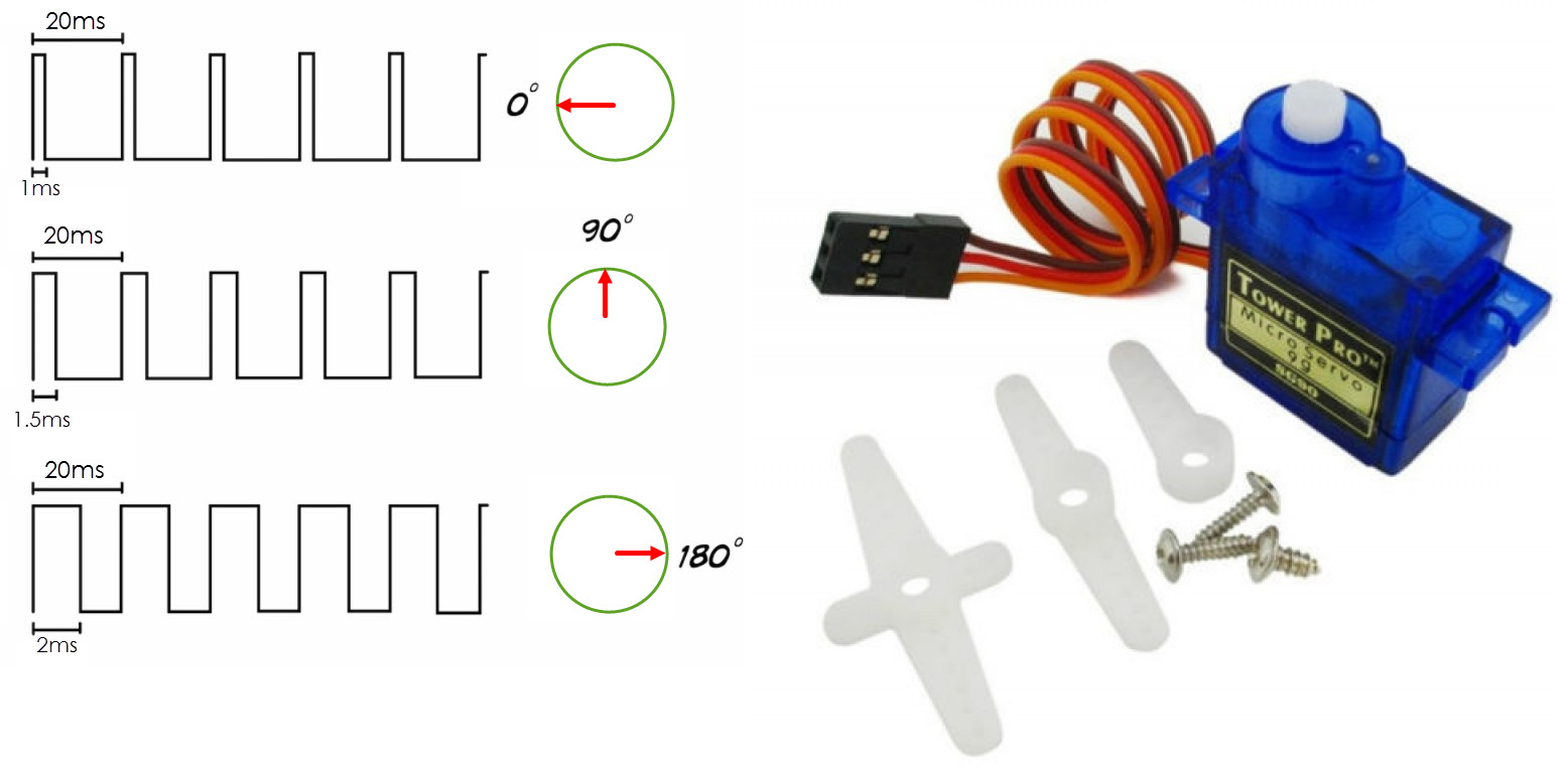
PWM period given for tower pro servo motor is 20 ms(in frequency domain 50 Hz). Operating frequency is 50 Hz(in time domain 20 ms). To rotate the arm head one must have to generate a PWM signal having period of 20 ms and signal duty cycle in between 0 to 2 ms.
  • Tower Pro Micro Servo SG90 9g moves to 90 degree on duty cycle of 1.5 ms.
  • Moves to 180 degree on duty cycle of 2 ms.
  • Moves to 0 degree on duty cycle of 1 ms.

One can easily rotate the arm at fixed angle by just varying the duty cycle. To move servo motor arm at 135 degree duty cycle will be 1.75 ms. Speed of arm can be controlled by changing the duty cycle very slowly. If duty cycle increases 2 ms servo arm will not come back to its position it will go out of order. In some servo motors if the duty cycle increases the maximum limit it will have no effect on arm, those particular servos not rotate their arm on duty cycles greater than their specifications.

Main 8051 microcontroller servo motor project

I am going to drive four servo motors with Atmel 89c52 microcontroller. Their are four push buttons. When ever push button is pressed the corresponding servo will rotate. Servo arm will move from 0 degree to 90 and then 180, after reaching 180 degree it will bring it back to initial zero degree position. Push buttons are connected to Port-1 Pin#0,1,2,3 of 89c51 microcontroller. Servo motors are connected to Port-2 Pin#0,1,2,3 of 89c51 microcontroller.

Tower pro servo motor has three wires colored red, yellow, black(brown). Apply +5 volts to red wire. Make black(brown) ground. Apply PWM(Pulse Width modulated) signal to yellow wire. Circuit diagram of 8051 servo motor project is given below.
Tower Pro SG90 9g servo motor with atmel 89c52 microcontroller.

8051 microcontroller servo motor - Main project working

When any push button is pressed the corresponding servo will rotate. 8051 microcontroller Port-1 is declared as input port and push buttons are connected to this port. When signal is high at Port-1 pin#0,1,2,3 servos will be off. When push button is pressed corresponding pin to push button will be grounded and servo will be actuated. Port-2 is declared as output port and servo motors are connected to port-2 Pin#0,1,2,3 of microcontroller. When any push button is pressed the corresponding pin on port-2 outputs a PWM signal. This pwm signal is input to servo pwm wire. This whole process is written in the code.

How pwm signal is generated using 8051 microcontroller?

PWM is generated using timers of 89c52 microcontroller. Timer-0 of 89c52 microcontroller is used for generating PWM signal. Now how PWM is generated using timers? To understand it you need to know what is PWM(Pulse Width Modulation).

PWM is a signal whose cycle has a high period for some time and low period for some time. It is same like digital signal which has high and low waves. In PWM method the high wave of the signal is varied. This high wave is know as PWM duty cycle(see the below picture).
Picture
Tower Pro SG90 9G servo Motor Duty Cycle and PWM Period
Tower PRO SG90 9g motor has a PWM period of 20 ms. In which 18 ms is low signal and 2 ms is variable high signal. To generate delay using 89c52 microcontroller you need to calculate the values for delay and load them in the timer register. I calculated the values for generating 18 ms,1 ms,1.5,1.8 and 2 ms delay and loaded them in the timer registers. TH0 and TL0 are timer registers. Here is a small tutorial link on how to calculate delay values?
  • Using Timers of 89c51, 89c52 Microcontroller for generating delays.  
The above link is very important to understand the code. If you don't go through the above tutorial you will be unable to understand the code below. Tower Pro servo SG90 9g has duty cycle from 1 ms to 2 ms. I calculated values for these delays. Made function for each value. When ever delay is needed i call the function.

The code in while(1) function is determining whether the push button is pressed? if pressed delay functions are called. These delay functions are actually PWM for the servo motor.  

Project Code

Download the project code from the links given at the bottom of the Post.


#include< reg52.h>
void ms1();
void ms1P5();
sbit Pwm_M1=P1^0;  //Input Pin for motor Actuation
sbit Pwm_M2=P1^1;  //Input Pin for motor Actuation
sbit Pwm_M3=P1^2;  //Input Pin for motor Actuation
sbit Pwm_M4=P1^3;  //Input Pin for motor Actuation

sbit M1=P2^0;	  //Output Pin for motor Actuation (PWM output pin)
sbit M2=P2^1;	  //Output Pin for motor Actuation (PWM output pin)
sbit M3=P2^2;	  //Output Pin for motor Actuation (PWM output pin)
sbit M4=P2^3;	  //Output Pin for motor Actuation (PWM output pin)


void Pwm_Low()	  //Generating 18ms delay
{

TH0=0xBF;
TL0=0x32;
TR0=1;       //Run Timer-0
while(!TF0); //Wait for T0 Interrupt Flag
TF0=0;       //Clear Interrupt Flag
TR0=0;       //Stop Timer-0
}


void Pwm_High()		 //Generating 2ms delay
{
TH0=0xF8;
TL0=0xCC;
TR0=1;       //Run Timer-0
while(!TF0); //Wait for T0 Interrupt Flag
TF0=0;       //Clear Interrupt Flag
TR0=0;       //Stop Timer-0
}

void ms1(){             //Generating 1ms delay
TH0=0xFC;
TL0=0x65;
TR0=1;       //Run Timer-0
while(!TF0); //Wait for T0 Interrupt Flag
TF0=0;       //Clear Interrupt Flag
TR0=0;       //Stop Timer-0
}

void ms1P5(){				//Generating 1.5ms delay
TH0=0xFA;
TL0=0x99;
TR0=1;       //Run Timer-0
while(!TF0); //Wait for T0 Interrupt Flag
TF0=0;       //Clear Interrupt Flag
TR0=0;       //Stop Timer-0
}


void main()
{
unsigned int i=0;
bit status=0;
P0=0x00;  //**** Port-0 Declared Output
P1=0xFF;  //**** Port-1 Declared Input
P2=0x00;  //**** Port-2 Declared Output
P3=0x00;  //**** Port-3 Declared Output

TMOD=0x01; //Timer-0, As 16-bit Timer.

while(1){
status=((P1>>0)& 1);                       //If push button is pressed
	
	if(status==0){		  	  //Motor-1
		for(i=0;i<100;i++){	
			M1=1;
			ms1();	
			M1=0;
			Pwm_Low(); 	 }
			
		for(i=0;i<100;i++){	
			M1=1;
			ms1P5();
			M1=0;
			Pwm_Low(); 	 }

		for(i=0;i<100;i++){	
			M1=1;
			Pwm_High();		 		
			M1=0;
			Pwm_Low();	  }

		for(i=0;i<100;i++){	
			M1=1;
			ms1();	
			M1=0;
			Pwm_Low(); 	 }	  
			  			  }
						 

status=((P1>>1)& 1); 
	if(status==0){	        //Motor-2
			for(i=0;i<100;i++){	
			M2=1;
			ms1();	
			M2=0;
			Pwm_Low(); 	 }
			
		for(i=0;i<100;i++){	
			M2=1;
			ms1P5();
			M2=0;
			Pwm_Low(); 	 }

		for(i=0;i<100;i++){	
			M2=1;
			Pwm_High();		 		
			M2=0;
			Pwm_Low();	  }	
	        
		for(i=0;i<100;i++){	
			M2=1;
			ms1();	
			M2=0;
			Pwm_Low(); 	 } 

		 }	 

status=((P1>>2)& 1);
	if(status==0){		   //Motor-3
		for(i=0;i<100;i++){	
			M3=1;
			ms1();	
			M3=0;
			Pwm_Low(); 	 }
			
		for(i=0;i<100;i++){	
			M3=1;
			ms1P5();
			M3=0;
			Pwm_Low(); 	 }

		for(i=0;i<100;i++){	
			M3=1;
			Pwm_High();		 		
			M3=0;
			Pwm_Low();	  }

		for(i=0;i<100;i++){	
			M3=1;
			ms1();	
			M3=0;
			Pwm_Low(); 	 }
		 }	 

status=((P1>>3)& 1);
	if(status==0){			    //Motor-4
		for(i=0;i<100;i++){	
			M4=1;
			ms1();	
			M4=0;
			Pwm_Low(); 	 }
			
		for(i=0;i<100;i++){	
			M4=1;
			ms1P5();
			M4=0;
			Pwm_Low(); 	 }

		for(i=0;i<100;i++){	
			M4=1;
			Pwm_High();		 		
			M4=0;
			Pwm_Low();	  }			
					
		for(i=0;i<100;i++){	
			M4=1;
			ms1();	
			M4=0;
			Pwm_Low(); 	 }
			}
}
}

More projects involving servo motors and microcontrollers. Each project is based on different microcontroller. Projects source code and circuits are open source. One can use and modify them according to his/her needs.
Servo motor controlled with 32 bit stm32 microcontroller
Servo motor controlled through WEB with nodemcu
Download the Project code and simulation. Folder contains the project code and hex file. Project is made in keil u-vision 4. Full keil project and files are in the folder. Simulation is made in Proteaus 8.0. You can see the PWM signal in the simulation. If you have any queries and questions write them below in the comments section.
Servo motor interfacing with 89c52 microcoontroller(code)